2003 – 2004 Cobra Blower Removal and Install
Tools needed: 1/4inch drive sockets (7,8,10,13mm), deep 10mm socket, socket extensions, pliers, screwdrivers, open end 10mm ratchet wrench, 13mm, 27mm, and 1 inch wrenches, extendible magnet (just in case), torx t-20 driver, 1/2 inch socket driver for blower belt, propane torch, inch/lb and ft/lb torque wrenches for installation
Other supplies: rags, towels, loctite (red), RTV (gasket maker), intercooler fluid, hose clamps, zip ties, brake or carb cleaner, zip lock bags.
TIPS: take your time, read through these directions, print them out, and go slow. i drained my intercooler fluid at the beginning of the job and it made things a lot cleaner, but this is not a must. be very careful about labeling EVERYTHING that is disconnected. i used masking tape, and black sharpee marker to label things. also use zip lock bags to put nuts/bolts/etc. in from each step, and label the ziplock bag. remember your blower will be away for a week or two and you don't want to forget/overlook anything. also have a friend handy when it comes time to lift the intake/blower up to get at the intercooler manifold bolts. i have no friends, so i had to use wood blocks to hold it up, but this is not ideal. also, you can reuse most of your gaskets so be careful with removal of items with gaskets. i had to pitch my plenum gasket and intercooler manifold gaskets.
Here's a quick list of nut/bolt sizes for quick reference: throttle body--four 8mm bolts, idle air control motor (IAC)--two 8mm bolts, throttle cable bracket--two 8mm bolts, intake plenum--four 13mm nuts, large driver's side bracket on blower--two 10mm bolts, one 10mm nut, EGR valve--one 10mm bolt, one 10mm stud, one 27mm nut, MAT sensor--two t-20 torx screws, fuel injector rail studs--four 10mm studs, intercooler manifold--three 10mm bolts, one 8mm bolt, blower bypass valve--two 10mm bolts, lower intake bolts--ten 10mm bolts, blower bolts--ten 10mm bolts, intercooler to blower bolts--10 7mm bolts
GASKETS--here's a list of gaskets to look out for/order if you're going to replace them. like i said, i needed to replace the intake plenum gasket and the intercooler manifold gasket, and i was careful in removing them.
throttle body to intake plenum, IAC motor to throttle body, intake plenum to supercharger, EGR valve to supercharger, intercooler manifold to lower intake manifold, blower to lower intake manifold, and lower intake manifold to cylinder heads
TORQUE SPECS: ten 7mm intercooler to blower bolts--tighten 1st to 2Nm (18inch/lbs) 2nd tighten to 6Nm (53inch/lbs) then go back through and make sure all are at 53inch/lbs--use red loctite, see pictures for sequence diagram
ten 10mm blower to intake bolts--tighten 1st to 2Nm (18inch/lbs), 2nd to 25Nm (18ft/lbs), and 3rd tighten an additional 90 degrees
ten 10mm intake to cylinder head bolts--tighten 1st to 50 inch/lbs, 2nd to 10 ft/lbs, and 3rd to 15 ft/lbs. EDIT--some people have said that the 15lb/ft is not the correct #, so please double check that #--its what i used when i did my ported eaton, and then whipple.
four intercooler manifold bolts (three 10mm, and one 8mm)--1st tighten to 10Nm (89inch/lbs), 2nd tighten an additional 90 degrees
fuel rail studs (four 10mm studs)--tighten to 10Nm (89inch/lbs), large 27mm EGR nut--tighten to 35Nm (26ft/lbs), four 13mm nuts for the intake plenum--tighten to 25Nm (18ft/lbs), two 10mm bolts on throttle cable bracket--tighten to 10Nm (89inch/lbs)
STEP BY STEP:
1. drain intercooler fluid. this is not a must, but eliminates a lot of spillage and mess. i did this by removing the hose clamp off my heat exchanger. if you don't do it this way, you should remove as much intercooler fluid from the reservoir as you can using a turkey baster.
2. disconnect battery.
3. remove your blower belt from the supercharger. to do this, use a 1/2inch socket drive and put it in the factory spring loaded tensioner. i believe you will turn the tensioner clockwise to let tension out, and you can remove your belt.
4. next remove the items in the picture below
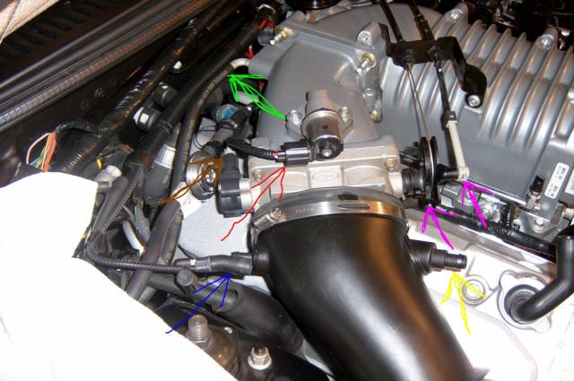
some of these are electrical connections (the throttle position sensor-brown arrow, and the IAC control harness-red arrow). also unhook your mass air harness (not pictured), but it is the wire connector to you mass air sensor.
others are vacuum lines i believe (there is one that hooks into the intake plenum-green arrow, and one that hooks into your air inlet tube-blue arrow)
next unhook the crankcase breather (yellow arrow), as well as the two throttle connectors (lavender arrows)--to remove these, the upper one just snaps out of its holder, and the lower one just slides out.
now you are ready to remove your air inlet tube (unscrew the large hose clamp holding the inlet tube to the throttle body), and remove whatever cold air intake you have as well.
5. remove the following pictured below
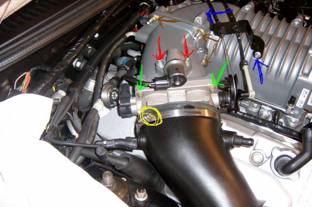
IAC motor-red arrows, two 8mm bolts, be careful with gasket
throttle body-green arrows, four 8mm bolts, again take care with gasket
throttle cable bracket-blue arrows, two 8mm bolts--zip tie cable off to side
intake plenum-four 13mm nuts, use the socket for some, and the open end wrench for the others, again take care with the gasket.
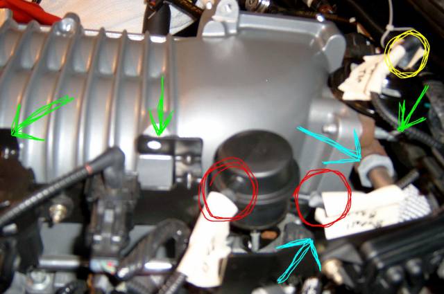
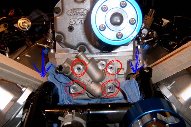
6. refer to picture below and remove the following
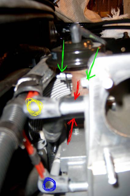
this is a view of the back side of the blower as seen from the passenger side, you can see on the right side of the picture the intake plenum has been removed.
first remove two vacuum lines and label them, from the back of the blower--the upper vac line (yellow circle), and lower vac line (blue circle)
you can then remove the PCV hose-two red arrows, that is just to the side of the upper vacuum line.
finally, remove one nut (left green arrow), and one bolt (right green arrow). both are 10mm. the nut is one of three things holding on a large driver's side bracket (that will soon be removed), and the bolt holds part of the EGR valve in place. once you remove the driver's side bracket, you will have to come back and remove the other bolt holding the EGR valve in place. you will need a ratcheting (preferably) 10mm wrench for this.
here's another look at the back of the blower, with the blower off the car when i just got it back from porting
the upper vacuum line is shown with the blue arrow, the lower vacuum line with the green arrow and the PCV hose attaches to the blower at the red arrow.
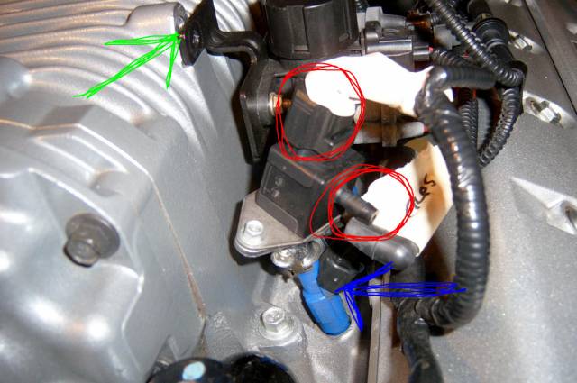
7. refer to piture below and remove the following
this is a view from the driver's side of the big bracket and EGR valve
remove the other two bolts--10mm, holding the large driver's side bracket on (the left two green arrows).
you will need to remove several other connections in order to pull this bracket and all that is attached to it away from the blower to give you room
remove two connections to the blower bypass valve--red circles
next remove the vacuum line going into the top of the EGR valve--yellow circle
then remove the large nut on the side of the EGR valve--upper blue arrow. i used a 27mm wrench to do this, but others have found the correct size is 1inch. you will find that the tube will remain inside the EGR valve.
the other lower blue arrow is pointing to the MAT sensor that is attached to the blower with torx screws. you may not be able to remove the electrical connector to the MAT sensor yet, but this is the only picture i have that shows the vicinity where it is, and it will have to be disconnected to get the blower out.
8. refer to the picture below
this is another view of the large bracket on the driver's side and the last few things that get disconnected before you can move it all to the side.
the green arrow is just one of the three connections of the bracket to the blower, remember one of them is back behind the EGR valve and the other is right next to the one in this picture.
the red circles show two connections to the fuel rail pressure sensor that should be disconnected.
now you can move the whole bracket off to the side. remember to go back to the EGR valve at this time and remove the (now exposed) bolt-10mm-using a ratcheting box end wrench. now you should be able to remove the EGR valve--again watch out for the gasket
as you do this, you'll want to disconnect the wiring harnesses to each of the four injectors on the driver's side (one is shown with the blue arrow)
now you should have sufficient room to get at the lower intake as well as the blower bolts on the driver's side. the fuel injectors themselves, as well as the fuel rails, do NOT get disconnected
9. refer to below
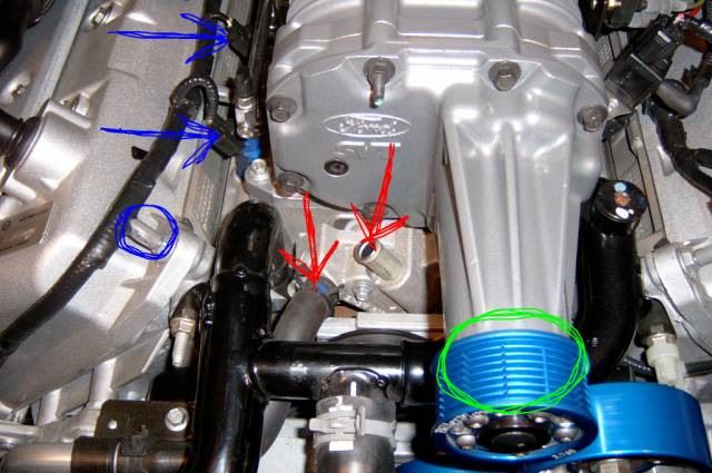
this is a frontal shot.
remove the inlet hose (red arrow on left), as well as the outlet hose (red arrow on right-hose is already removed) from the intercooler manifold. again, if you didn't drain all the IC fluid, you may get some spillage, so be prepared
now remove all the injector wiring harnesses on the passenger side-blue arrows, and pull all that wiring off to the side. now the passenger side is completely exposed.
the blower belt (green circle) should be removed at this point
10. refer to picture below
next, loosen, but do not remove the four studs that hold the fuel rails to the blower/intake--i believe 10mm deep socket. there are two studs per side. it is only necessary to back them out a fair amount, because you will have to rock the fuel rail to one side to get at the blower bolts in a later step. again, there is NO NEED to disconnect the fuel rails or injectors at all.
the blue arrows are pointing at 2 of the ten bolts (5 per side) that hold the lower intake to the cylinder heads--remove these bolts at this time, they are 10mm bolts. be careful with the back ones on each side, so they don't fall behind your engine. i put down a blue rag on each side to prevent this.
at this time, the only thing connecting your lower intake/blower to the rest of the engine is the fuel lines hooking into the fuel rails on the passenger side. DO NOT disconnect this line. it is flexible, and you will be ok not disconnecting it. the whole point of removing the lower intake bolts is so that your friend (please call friend at this time) can tilt the lower intake up in the air slightly so you can remove the intercooler manifold--next step
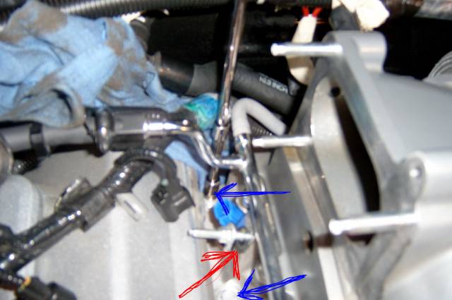
11. refer to below
this is a frontal shot, with the lower intake/blower combo tilted in the air by your friend (which happened to be two wooden slabs in my case-blue arrows)
now remove the four bolts holding the intercooler manifold to the lower intake. three are 10mm and one is an 8mm bolt. if you didn't drain your IC fluid, get ready for splillage. now while the blower is still tilted up, carefully remove the intercooler manifold and the two connectors (next picture) that fit into the intercooler itself. these connectors are held in place by o-rings. again, be careful to try to save the gasket.
now set your lower intake back into place. be careful in doing this so that you do not put it back down crooked, or you will ruin the gasket below. at this time i put four of the ten lower intake bolts back into place (hand tight), just to hold the intake down when removing the blower itself.
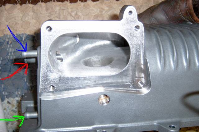
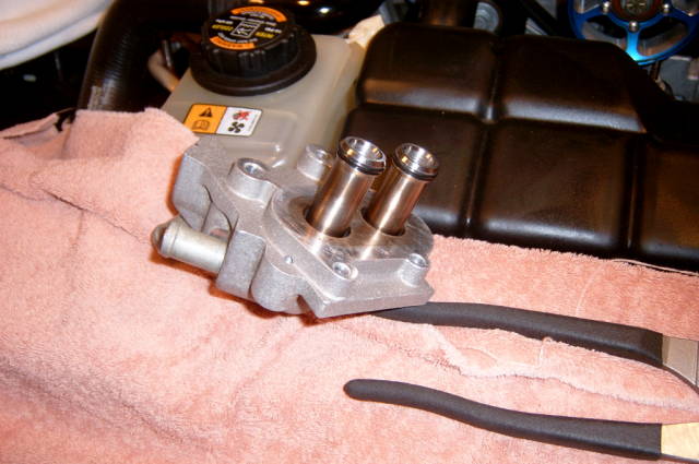
below is the intercooler manifold, removed, showing the two connections to the actual intercooler
12. next, remove the ten 10mm bolts holding the blower in place. you will have to tilt the fuel rails back slightly to get at the bolts. again, watch it with the back bolts so you don't lose them.
now confirm that all connectors to the blower are not attached. the only two things on the blower at this time should be the bypass valve and the MAT sensor. make sure all connections to both of those are removed.
lift the blower straight up, and out of your engine. use your friend, be careful, it will be much heavier than you think--it still has the intercooler attached. be careful with the blower gasket if you want to reuse it
13. drain the last of the IC fluid from the IC by tilting the blower on its end--be careful, don't drop your blower. now remove the MAT sensor using a t-20 torx screwdriver. then you can remove the blower bypass valve-two 10mm bolts, it will take some fiddling to remove it but take it off.
14. last, but not least, remove the intercooler from the blower. this takes patience and eight 7mm bolts. use the propane torch to break the loctite that is holding these bolts in. if you meet resistance, take a 1/4 turn backwards and then go again. i didn't use the torch and broke one off. if you do this, stegy can drill it out for around $20.
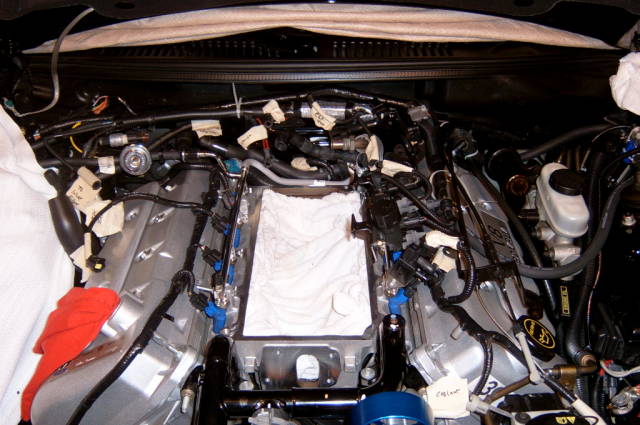
your engine bay should look like this
use a towel to block off the intake
there you have it. it took me at least 4 hours, but as you can see from the above write-up, i'm anal about these things. good luck!!
INSTALLATION
Here are some pics and tips on the installation of your blower:
refer to the top of the thread for necessary tools and equipment--you will need inch/lb and foot/lb torque wrenches, as well as red loctite and some gasket making material.
one important thing to keep in mind when you are torqueing bolts down is not to get confused between inch/lbs and ft/lbs. if a torque step says to tighten something to 53 inch/lbs and you go with ft/lbs instead, you will break the bolt for sure--so pay close attention
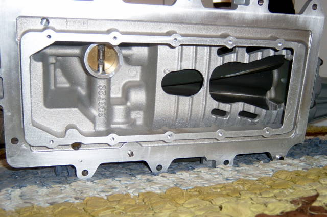
here's a picture of my port job
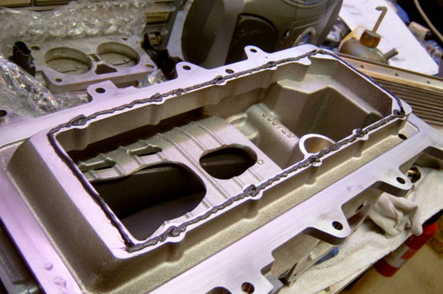
here's a picture of the blower off the car and upside down with a bead of gasket making material on it between the blower and the intercooler:
now place the intercooler on top of the blower (MAKE SURE THE INTERCOOLER INLET AND OUTLET PIPES ARE FACING THE FRONT OF THE BLOWER) and start all ten 7mm intercooler bolts (THESE SHOULD NOT BE RE-USED). use a dab of RED loctite on these bolts. refer to the crude picture below for the proper torque sequence:
(I got all of these torque numbers from cobrabob's website--and he had gotten them from a ford manual i think)
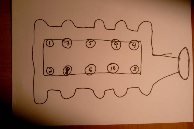
1st tighten to 2Nm (18 inch/lbs) NOT FT/LBS!!!!
then tighten to 6Nm (53 inch/lbs)
i went through one more time to make sure each bolt was at 53 inch/lbs
this must be done within 5 minutes of starting the torque sequence for some reason
once you have the intercooler attached to the blower, its time to bolt on the MAT sensor and the blower bypass valve. i'm not sure if there's any specific torque setting for these, but they must be put on before the blower is bolted back up the the lower intake. the blower bypass valve uses two 10mm bolts and the MAT sensor uses two t-20 torx screws.
i then placed a very thin coat of gasket maker on the blower gasket and then placed the blower in position (with the help of a friend this time) on top of the lower intake. before you do this, inspect your car's engine bay and make sure the lower intake is clean and clear of any debris/tools/etc., and also make sure that the path is clear for the blower to go back on top of the intake.
the crude picture below shows the torque sequence for both the ten 10mm blower to intake bolts (the inner set of numbers) as well as the ten 10mm intake to cylinder head bolts (outer set of numbers). only bolt the blower to the intake at this time, as you will have to lift the blower/intake combo up in the air again to bolt the intercooler manifold in place.
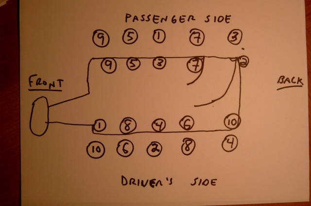
these are the specs listed: blower to intake bolts
1st tighten to 2Nm (18 inch/lbs) INCH POUNDS!!!
2nd tighten to 25Nm (18 ft/lbs) FOOT POUNDS!!!! (I took an additional step between 2Nm and 25Nm, as this seemed like too large of a jump)
3rd tighten an additional 90 degrees---it worked out to about 25 ft/lbs
next use your buddy to lift the lower intake/blower combo up in the air slightly so you can bolt on the intercooler manifold--if you used 4 of the lower intake bolts to hold the lower intake in place while your blower was being ported, make sure to remove these now.
the intercooler manifold bolts (three 10mm and one 8mm) bolt on in the following torque sequence
1st tighten to 10Nm (89 inch/lbs) INCH POUNDS!!!
2nd tighten an additional 90 degrees
now its time to bolt the lower intake to the cylinder heads. refer to the last picture for the torque sequence.
i didn't see specific #'s for this step, to i just went with the following:
1st tighten them to 50 inch/lbs
2nd tighten them to 10 ft/lbs
lastly tighten them to 15 ft/lbs (i always go through one last time to make sure all bolts are at the final torque spec)
if you labeled all the nuts/bolts/sensors/etc. properly, the rest of the installation should be pretty straight-forward. please refer to the blower removal for any pics that you may need showing where certain things go. don't forget to add intercooler fluid to your car. i like to "jump" the intercooler pump before i start my car so that i can circulate all the intercooler fluid and add any if necessary. i'll post a pic soon showing how to jump the intercooler pump.
here are a few of the other torque specs: throttle cable bracket--two 10mm bolts tighten to 10Nm (89 inch/lbs), intake plenum nuts--four 13mm nuts tighten to 25Nm (18 ft/lbs), large EGR valve nut--one 27mm nut tighten to 35Nm (26 ft/lbs), and finally the fuel rail studs--four 10mm studs tighten to 10Nm (89 inch/lbs).
the finished product:
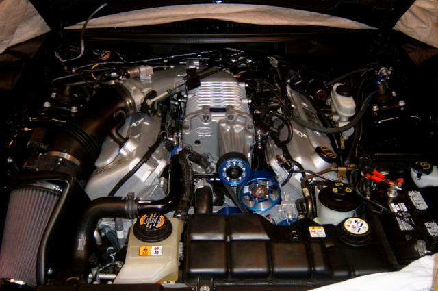
GOOD LUCK AND ENJOY!! |